Asset Fitter
What Is the Asset Fitter?
The Asset Fitter allows for precise adjustments to optimize how a Deformable is fitted to a Shape.
Setting Up an Asset Fitter
You can create an Asset Fitter for each Deformable or drag in an existing one. To create a new Asset Fitter, right-click on the Deformable and select Create → Asset Fitter.
Below we show how to create or drag an Asset Fitter into Business_Top, under the Heavy Shape.
Creat an Asset Fitter
Drag and Drop an Asset Fitter
Important Notes
- Currently, an Asset Fitter can only be applied to a Deformable within a Shape, not within its Template.
- Customizing the Fitter Meshes: You can control which meshes from the Template are used during asset fitting - by default, all meshes are referenced. To customize this:
- Select the Template to access the Template Component
- In the Fitter Meshes section, use the ‘+’ or ‘-’ buttons to add or remove meshes as needed.
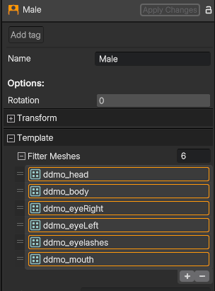
Fitter Meshes in Template Component
Configuring the Asset Fitter
For each Asset Fitter, you can specify the deformation method type, apply expansion to make the Deformable fit more loosely, and define stiff regions, i.e., areas where the fitted Deformable should keep the same shape as in the template Deformable in some sense. Once everything is set, click Apply Changes to see the fitted Deformable.
More details on configuring each parameter are provided below:
- Deformer – choose the deformation method to fit the Deformable to the Shape:
- Fast – Produces an approximate fit by balancing between speed and quality. The result is usually correct if the deformable fits tightly to the shape.
- Accurate – Produces usually better quality results than the fast option, ensuring physically plausible deformations to the template deformable, though at the cost of increased processing time.
- Expansion – apply this setting to make the Deformable fit more loosely around the Shape. The expansion defines a minimum gap (in centimeters) between the Shape and the Deformable. This can be useful to reduce intersections.
- Stiff Regions – define as many regions as needed, to specify where the Deformable should be stiff in the sense that it does not change shape. For each stiff region, link the appropriate UV Masks to the respective deformable meshes. You can also customize the Stiffness Type and Bleeding for each region. See more details below in How to Apply Stiff Regions
Why Is Stiffness Important?
When fitting a Deformable into a Shape, regions that should remain stiff - like metallic pieces, armatures, fabric patterns - can deform unexpectedly. Applying stiff regions helps maintain the desired structure during deformation.
In the following example, we can see a shirt where the logo loses its form when deforming to the Heavy shape. By applying stiffness to that region, the logo's proportions are preserved compared to when stiffness is skipped.

Shirt fitted to Heavy Shape - No Stiffness
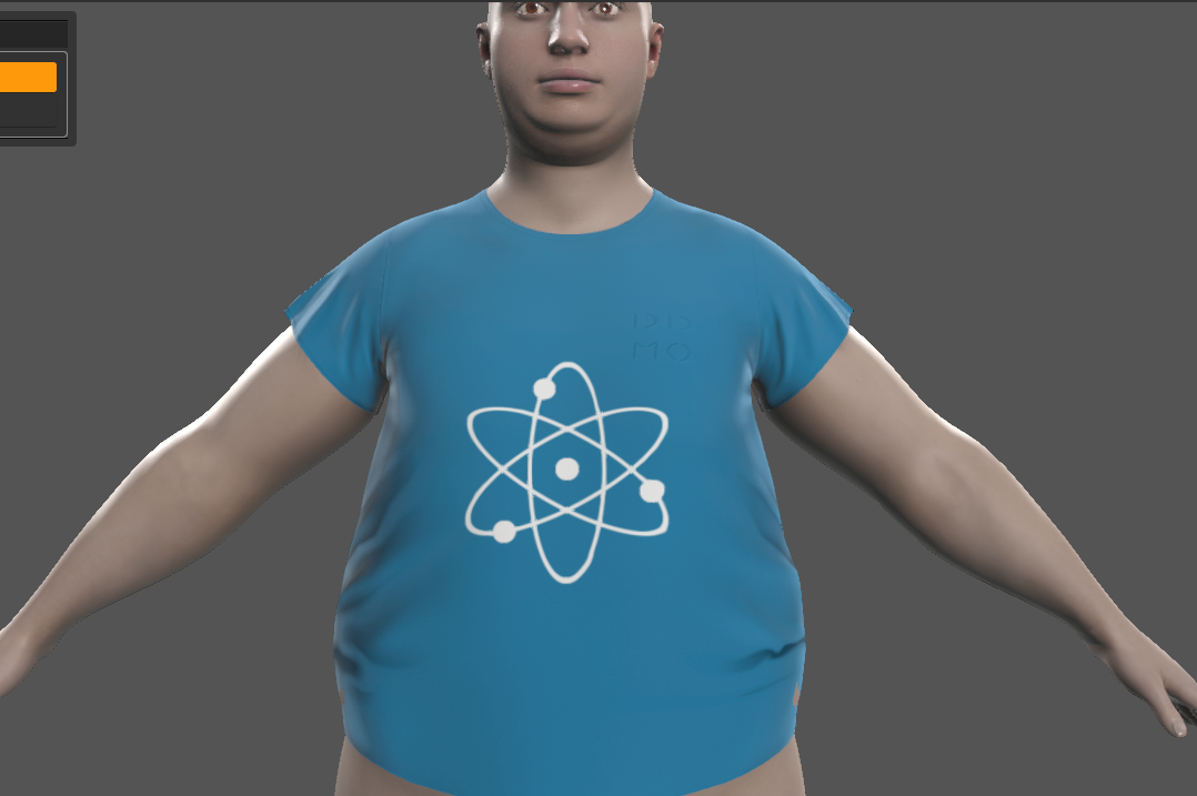
Shirt fitted to Heavy Shape - With Stiffness
In another example, when fitting a hat to a Goblin shape, the back and brim deform poorly due to the shape's features. Adding stiffness to these regions ensures a better fit, maintaining the hat’s intended form.
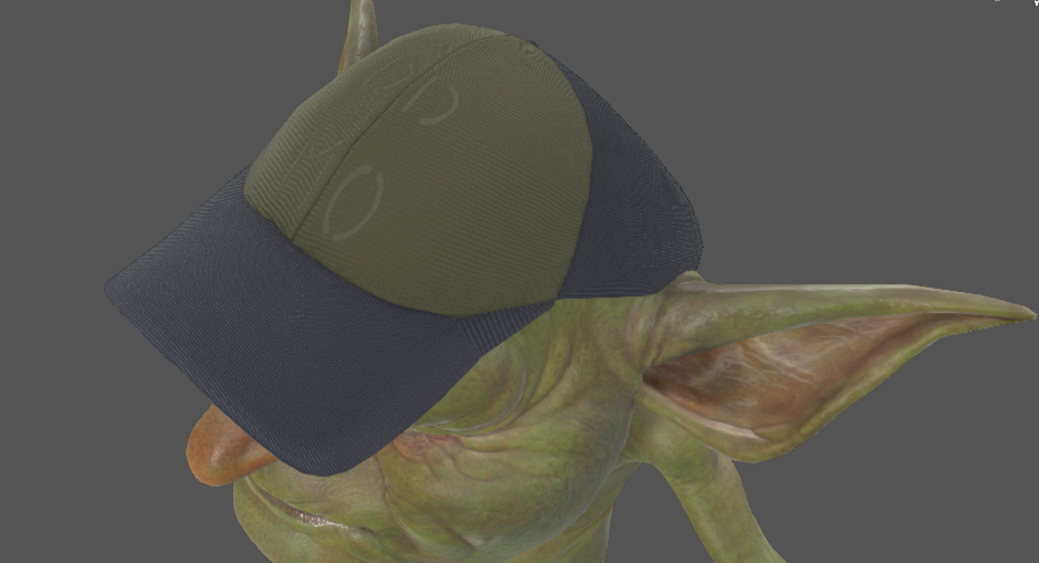
Hat Fitted to Goblin Shape — Brim Region with Stiffness
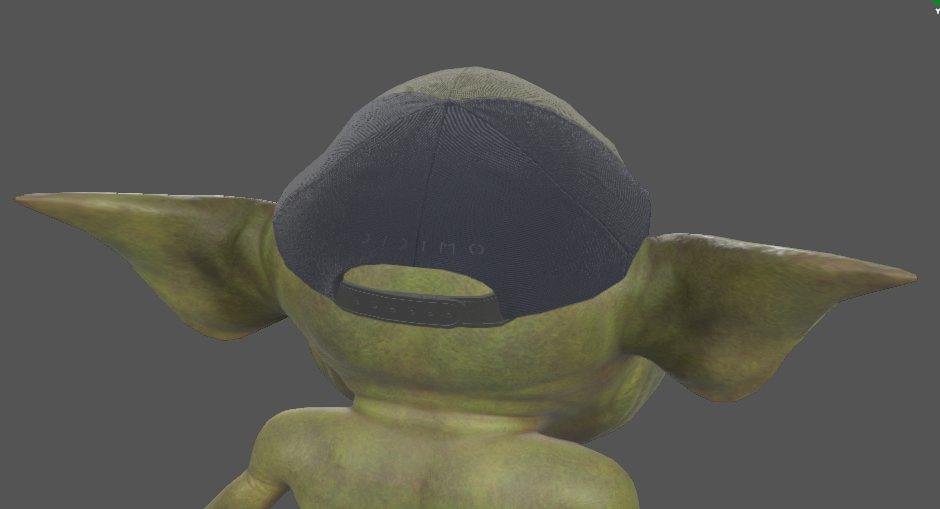
Hat Fitted to Goblin Shape — Back Region with Stiffness
How to Apply Stiff Regions
Stiff Regions allow you to control the stiffness of a Deformable when fitting it to a Shape. Within each Stiff Region, you can link UV masks to define which areas remain stiff and which remain flexible.
Below are the steps to apply a Stiff Region, using the Business_Top under the Heavy Shape as an example.
Step 1: Creat a Mask (External Application)
If you haven’t created one already, you can create your stiffness mask using a 3D modeling software (e.g., Maya, Blender). Here's a general process to generate a single mask:
1.1. Import the Deformable and Select the Target Mesh
Import the Deformable into your software and select the specific mesh where you want to define stiffness. Ensure the mesh has proper UV mapping, as the stiffness mask will be applied based on UV coordinates.
1.2. Paint the Mask
Use your software’s available painting tools to define stiffness regions. The exact method varies by software (e.g., texture painting, or vertex painting).
We support binary masks: white areas → stiff; black areas → flexible.
💡 For precise stiffness boundaries, use hard-edged brushes or selection tools
1.3. Export the Mask
Save the mask in a standard image format, preferably in a lossless image compression format (e.g., PNG, JPEG). Ensure the resolution is large enough to capture the necessary region definition details (we recommend to use 2K or higher).
📌 Tutorial (Maya)
Here we create a mask for the Business_Top Deformable, targeting the Business_Top mesh.
Step 2: Import the Mask(s)
- In Popul8, right-click on the Project panel and select Import → Files.
- Choose the binary mask file created in Step 1 and import it.
- The imported mask(s) will appear in the Project window.
📌 Tutorial
Step 3: Configure Stiff Regions
3.1. Assign the Mask(s) to a Stiff Region
- Navigate to the Deformable you want to modify.
- If you haven’t done so already, create an Asset Fitter: right-click on the Deformable and select Create → Asset Fitter
- Within the Asset Fitter, set up the Stiff Regions:
- Add as many Stiff Regions as needed - one per area requiring stiffness.
- Each Stiff Region can have multiple UV Masks.
- In each UV Mask, the corresponding Deformable meshes are automatically assigned.
- Link the imported mask(s) to the respective meshes.
📌 Tutorial
3.2: Adjust Settings (If Applicable)
- Stiffness Type – Determines the stiffness transformation applied to the region:
- Translation → Pure translation
- Scaling → Isotropic scaling + translation
- Rigid → Translation + rotation
- Similarity → Isotropic scaling + rigid
- Affine → General parallel-preserving transformation
- Bleeding (cm) – Controls how much influence the Stiff Region has on surrounding Deformable vertices:
- 0 cm → No influence beyond the defined region (may lack smoothness)
- Higher values → Gradual blending into surrounding areas
Step 4: Apply Changes
Once everything is set, click the Apply Changes button at the top! You can now observe how the masks influence the fitted Deformable and adjust the masks or settings as needed.
Notes & Considerations - Stiff Regions
- Overlapping UVs: Regions with overlapping UVs are split into connected components (in the sense of the Deformable mesh edge connectivity) and treated as independent stiff regions.
- Submesh Support: A current limitation of stiff regions for Deformable meshes that have sub-meshes is that the sub-meshes are assumed to share the same UV space. Unintended results may be produced if sub-meshes have distinct UV spaces.
Updated about 1 year ago